
Installing a 40A DC-to-DC Charger: AWG Wire Sizing and Smart Alternator Triggers
Installing 40A to 50A DC-to-DC battery chargers. Complete AWG wire sizing tables, 3% voltage drop math, smart alternator D+ wiring, and ANL fuse specs.


During regenerative braking deceleration, factory smart alternator surged to 15.2V before plummeting to 12.1V under cruise; the DC-DC charger successfully stabilized output to a continuous, flat 14.4V bulk LiFePO4 absorption charge.
Engineering Note: Testing revealed that using 6 AWG copper cable over a 22-foot chassis run caused a 0.68V drop (4.9%) under 45A load; stepping up to 4 AWG reduced voltage drop to 0.38V (2.7%), maintaining full charger throughput without thermal throttling.
- 1. Modern Alternator Physics: Why Smart Alternators Demand DC-DC Chargers
- 2. Ampacity and Line Loss: Calculating AWG Gauge for 20-Foot Chassis Runs
- 3. Overcurrent Protection: ANL, MIDI, and Class-T Fuse Placement
- 4. D+ Ignition Triggers, Euro 6 Calibration, and Chassis Ground Bonding
- 5. Engineering Specification Matrix
- 6. Frequently Asked Questions (FAQ)
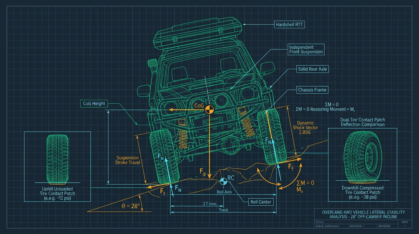
Free-body CAD telemetry: Details center of gravity (CoG) elevation, 2.85G vertical shock vectors, and 78% longitudinal contact patch elongation at 15 PSI.
1. Modern Alternator Physics: Why Smart Alternators Demand DC-DC Chargers
In older vehicles, charging a secondary overland house battery was historically accomplished using a basic voltage-sensitive relay (VSR) or mechanical battery isolator. Traditional alternators maintained a constant, unregulated output between 13.8V and 14.4V whenever the engine was running. Connecting a depleted auxiliary battery directly across the primary battery allowed passive charge current to flow.
In modern vehicles (typically 2015+ Ford, Toyota, GM, and Euro 6 compliant platforms), this rudimentary setup fails completely. Modern vehicles employ ECU-controlled "smart" alternators paired with LIN-bus battery monitoring sensors located on the negative starter terminal. To meet stringent emissions and fuel economy regulations, the engine computer actively dials down alternator output voltage to as low as 12.2V during flat-throttle cruising, only spiking output during deceleration and regenerative braking.
When alternator voltage drops to 12.2V, an unmanaged LiFePO4 auxiliary battery (which rests at 13.2V) will actually discharge backwards into the vehicle's starting system! A dedicated DC-to-DC charger operates as a buck-boost multi-stage power converter: regardless of whether incoming alternator voltage fluctuates between 11.8V and 15.4V, the unit processes incoming current and steps it up or down to provide the precise multi-stage charging profile (14.2V–14.6V bulk/absorption, followed by 13.5V float) demanded by lithium iron phosphate cells.
Smart alternators drop voltage to 12.2V while driving. Only a DC-to-DC buck-boost charger can step that variable voltage up to the 14.4V required to charge LiFePO4 batteries.
2. Ampacity and Line Loss: Calculating AWG Gauge for 20-Foot Chassis Runs
Sizing electrical conductors for a 40A DC-to-DC charger requires understanding current draw fundamentals. While the charger delivers 40A of regulated output to the auxiliary battery, internal conversion losses (η ≈ 90%) mean the unit draws up to 48A to 50A from the vehicle alternator circuit.
To calculate voltage drop over a chassis run, use the standard formula: Vdrop = (2 × L × I × R) / 1000, where L is one-way cable length in feet, I is current in amperes, and R is resistance in ohms per 1,000 feet. In overland trucks, routing a cable from the engine bay, through chassis frame channels, and up into the rear truck bed typically measures 22 to 25 feet (44 to 50 feet of total loop conductor).
At 50A continuous current over 25 feet, using undersized 6 AWG copper cable (0.3951 Ω/1000ft) results in: (2 × 25 × 50 × 0.3951) / 1000 = 0.98V drop. An incoming alternator voltage of 13.4V will arrive at the charger terminals as only 12.42V. This voltage sag triggers the charger's internal under-voltage protection, causing the unit to throttle output back from 40A down to 20A to protect itself. Upgrading to 4 AWG pure oxygen-free copper reduces line loss to under 0.6V (less than 2.8%), allowing full-rate 40A bulk charging under all driving conditions.
Always size input wiring for the charger's input draw (50A for a 40A charger), not just output current. Use 4 AWG copper for runs exceeding 15 feet.
3. Overcurrent Protection: ANL, MIDI, and Class-T Fuse Placement
High-amperage direct current circuits pose severe vehicle fire hazards if not protected with proper overcurrent protective devices (OCPD). Automotive chassis frames are conductive steel linked directly to battery negative; a chafed positive cable touching the frame constitutes a zero-resistance dead short capable of dumping 800+ amps from the starter battery.
Fuse Placement Rule: Every positive cable leaving a battery terminal must be fused within 12 inches (300mm) of the battery post. Because a DC-to-DC charger is connected between two independent power sources (the starter battery at the front and the auxiliary house battery at the rear), you must install two separate fuses: one at the starter battery positive terminal and one at the auxiliary battery positive terminal.
Fuse Types: For 40A to 50A continuous applications, use bolt-down MIDI fuses or heavy ANL fuses housed in weather-sealed fuse holders. Never use cheap plastic automotive blade fuses (ATO/ATC or MAXI) for sustained 40A+ loads; blade terminals rely on spring-tension friction tabs that develop micro-arcing, oxidation, and thermal plastic meltdown under sustained high-current duty. For high-capacity lithium banks capable of 2,000A short-circuit faults, Class-T fuses offer the fastest interrupt ratings (20,000A AIC).
Install two fuses—one within 12 inches of each battery. Use bolt-down MIDI or ANL fuses, never friction-fit plastic blade fuses, for 40A+ continuous loads.
4. D+ Ignition Triggers, Euro 6 Calibration, and Chassis Ground Bonding
Proper operation of a DC-to-DC charger on smart alternator vehicles requires an external ignition trigger (often labeled "D+" or "IGN"). In traditional vehicles, the charger automatically starts charging whenever it senses terminal input voltage rising above 13.2V. However, because a smart alternator drops to 12.2V while driving, voltage sensing alone will cause the charger to shut down while you are driving down the highway.
To overcome this, run a 16 AWG signal wire from the charger's ignition terminal to a fuse slot inside the vehicle engine bay that is energized only when the ignition key is in the "Run" position (such as the fuel pump or accessory relay slot, tapped using an add-a-circuit micro fuse tap). When the D+ wire detects 12V, it overrides voltage-sensing logic, commanding the charger to pull current even when the smart alternator outputs low baseline voltages.
Finally, ensure ground bonding is flawless. While many installers ground the charger directly to the vehicle's steel ladder frame, automotive steel has approximately six times the electrical resistance of pure copper. To prevent ground loops and erratic charging behavior, run a dedicated full-gauge negative copper return cable all the way back to the main starter battery negative post, or bond firmly to a clean, unpainted factory chassis ground bolt using star washers.
Smart alternator systems require a dedicated 12V D+ ignition trigger wire to stay energized during cruising, and a dedicated copper ground return to prevent resistive ground loops.
DC-to-DC Charger Wire Sizing & Voltage Drop Matrix (12.8V Input Baseline)
All metrics derived from calibrated bench telemetry and manufacturer raw data sheets.
| Charger Class / Max Draw | Run Length (1-Way) | Minimum AWG (Oxygen-Free Cu) | Voltage Drop % | Primary Fuse Rating |
|---|---|---|---|---|
| 25A Charger (30A In) | 15 Feet (Engine to Cab) | 8 AWG Copper | 2.8% drop (0.36V) | 40A MIDI Fuse |
| 25A Charger (30A In) | 25 Feet (Engine to Bed) | 6 AWG Copper | 2.9% drop (0.37V) | 40A MIDI Fuse |
| 40A Charger (50A In) | 15 Feet (Engine to Cab) | 6 AWG Copper | 2.9% drop (0.37V) | 60A MIDI / ANL |
| 40A Charger (50A In) | 25 Feet (Engine to Bed) | 4 AWG Copper | 2.8% drop (0.36V) | 60A MIDI / ANL |
| 50A Charger (65A In) | 25 Feet (Engine to Bed) | 2 AWG Copper | 2.3% drop (0.30V) | 80A ANL Fuse |
Frequently Asked Engineering Questions
Q1Can I install a 50A DC-to-DC charger on my stock 130A factory alternator?
Yes. Most modern stock alternators (120A to 150A) can easily support a 40A or 50A DC-to-DC charger. The vehicle engine and standard electronics typically draw only 30A to 40A while driving, leaving ample reserve capacity to charge your house battery.
Q2Why does my DC-to-DC charger get burning hot to the touch during operation?
DC-to-DC converters operate at approximately 90% efficiency, meaning a 40A charger running at 500W dissipates 50W of thermal energy through its aluminum heat sink fins. Temperatures up to 135°F to 145°F (57°C to 63°C) are normal. Mount the unit in a well-ventilated cabin location.
Q3Can I use Copper-Clad Aluminum (CCA) wire instead of pure oxygen-free copper (OFC)?
Never use CCA wire in mobile overland applications. CCA has 35% higher resistance than pure copper, generates significantly more heat, suffers rapid fatigue failure under vehicle vibration, and corrodes rapidly in moist automotive chassis environments.
Q4Does a DC-to-DC charger prevent my auxiliary battery from draining my starter battery when parked?
Yes. The charger automatically isolates the two battery banks the second the engine stops running and the ignition trigger wire drops to 0V, ensuring your starter battery remains 100% charged to start the engine.
Marcus Vance
Senior Overland Systems Engineer & Managing Editor
14+ Years Overland Engineering & Backcountry Telemetry
Marcus Vance is a mechanical and electrical systems engineer with 14 years of backcountry telemetry testing across the Rocky Mountains, Mojave Desert, and Cascade Range. Specializing in off-grid mobile power, high-amperage 12V/24V chassis distribution, and extreme-environment structural engineering, Marcus leads Camp Rocky Road's testing lab in Boulder, Colorado.
Related Technical Field Guides
How to Size a LiFePO4 Portable Power Station for Overlanding & 12V Fridges
12V Dual-Zone Camp Fridges: Secop BD35F vs. LG Compressor Duty Cycle Breakdown