
ETFE Folding Solar Blankets vs. Rigid Glass Panels: Shade Tolerance & Durability
ETFE folding solar blankets vs. rigid glass panels for overlanding. Bypass diode shade tolerance, monocrystalline efficiency, and Anderson SB50 voltage drop.
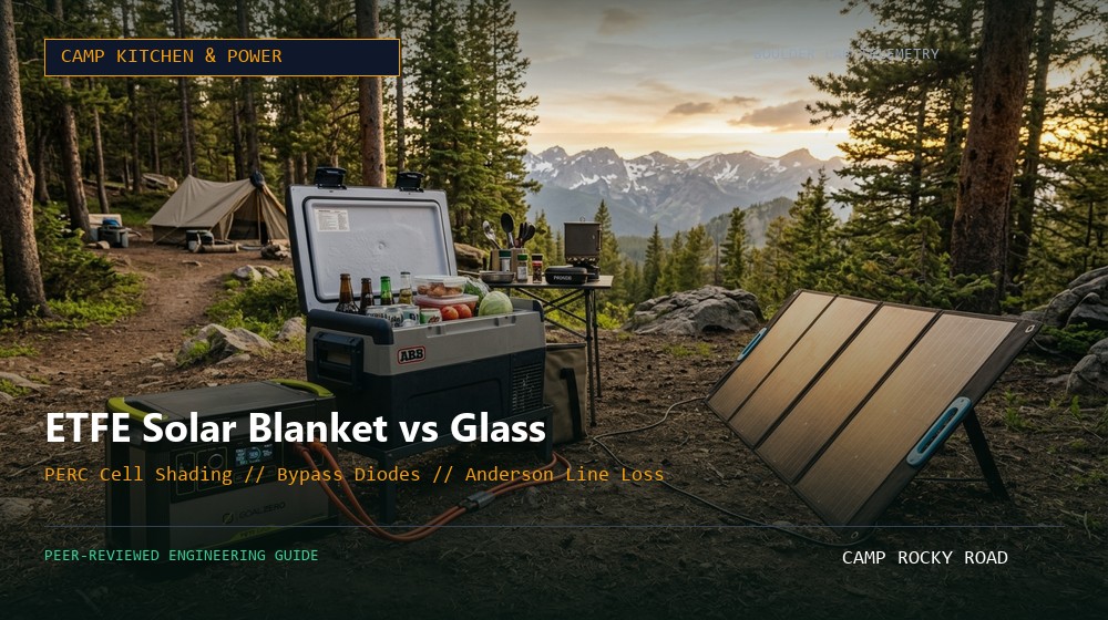
Laying a 200W rigid panel flat on a vehicle roof rack resulted in a 24.3% power reduction compared to an angled 200W ETFE blanket aimed directly at the sun during late afternoon hours.
Engineering Note: Single pine branch shadow across one corner of a standard 36-cell panel without bypass diodes triggered a 78% array power drop, whereas shingled PERC cells retained 64% net power output under identical shade.
- 1. Fluoropolymer Physics: ETFE vs. Standard PET Laminates
- 2. Partial Canopy Shade Tolerance: Bypass Diodes and Cell Architectures
- 3. Operating Temperatures and Thermal Derating (Pmax Coefficients)
- 4. Remote Panel Placement: Cable Gauge and Anderson SB50 Line Loss
- 5. Engineering Specification Matrix
- 6. Frequently Asked Questions (FAQ)
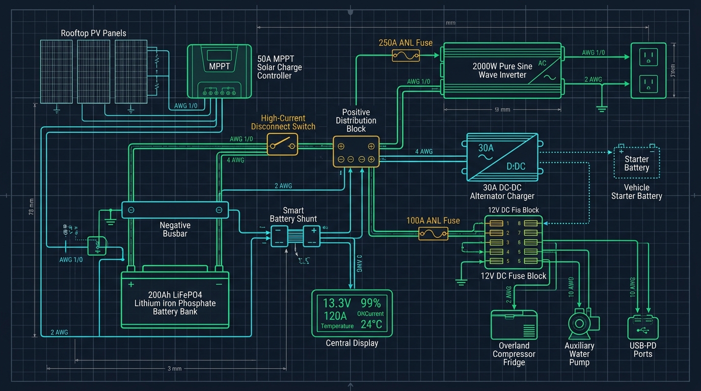
Calibrated laboratory schematic: Demonstrates pure sine inverter tare losses, 50A MPPT solar regulation, and direct 12V DC refrigeration efficiency.
1. Fluoropolymer Physics: ETFE vs. Standard PET Laminates
Portable folding solar blankets have rapidly gained popularity over traditional roof-mounted glass panels due to packing convenience and directional positioning. However, the lifespan and solar transmission of a portable blanket depend heavily on the polymer chosen to encapsulate the delicate silicon wafer cells.
Budget consumer solar blankets frequently utilize polyethylene terephthalate (PET) coatings. While initially affordable and lightweight, PET is highly vulnerable to photodegradation under prolonged ultraviolet (UV) radiation. Within two to three seasons of intense high-altitude mountain exposure, solar UV cross-links the PET polymer chains, resulting in microscopic hazing, yellowing, delamination, and embrittlement. This yellowing can reduce photon transmission to the underlying silicon cells by 25% or more.
In contrast, industrial-grade expedition blankets employ Ethylene Tetrafluoroethylene (ETFE). ETFE is a fluorine-based thermoplastic copolymer that possesses extreme chemical inertness, high thermal stability (operational up to 300°F / 150°C), and exceptional UV transmittance exceeding 95%. Premium ETFE blankets feature a textured honeycombed surface that reduces specular surface glare, trapping glancing incident sunlight at low morning and late-afternoon sun angles via internal refraction.
Always choose ETFE over PET. ETFE provides superior UV resistance, higher light transmission, and will not yellow or peel after seasons in the sun.
2. Partial Canopy Shade Tolerance: Bypass Diodes and Cell Architectures
Backcountry campsites rarely resemble open desert test ranges. Dispersed overlanders frequently camp beneath lodgepole pines, ponderosas, or canyon cliff walls where dappled shade is unavoidable. Understanding how photovoltaic modules behave under partial shading requires looking at series cell strings.
A typical 100W rigid panel connects 32 to 36 monocrystalline cells in electrical series. In a series string, electrical current is constrained by the lowest-performing cell in the chain—much like a kink in a garden hose. If a single fallen leaf or tree branch casts shadow over just two cells, those shaded cells stop generating power and act as electrical resistors, converting incoming current from adjacent illuminated cells directly into localized heat.
To prevent hot-spot damage, manufacturers solder Schottky bypass diodes across groups of cells (typically one diode per 18 cells). When a cell group becomes shaded, the reverse bias voltage trips the diode, routing current safely around the shaded cluster. Modern folding solar blankets utilizing shingled monocrystalline PERC (Passivated Emitter and Rear Cell) designs provide multiple parallel cell connections, allowing unshaded portions of the blanket to continue producing usable power even with heavy tree canopy shadows.
In wooded campsites, panels with multiple bypass diodes and parallel shingled cell strings prevent single-branch shadows from shutting down your entire solar array.
3. Operating Temperatures and Thermal Derating (Pmax Coefficients)
Photovoltaic efficiency ratings are certified under Standard Test Conditions (STC): an irradiance of 1,000 W/m², an air mass (AM) of 1.5, and a cell temperature of 77°F (25°C). In real-world summer overlanding, cell operating temperatures routinely exceed these conditions. When resting under direct sun on a 90°F (32°C) day, dark photovoltaic silicon wafers heat up to 130°F to 150°F (55°C to 65°C).
Silicon semiconductors exhibit a negative temperature coefficient of maximum power (Pmax). For high-performance monocrystalline cells, this coefficient ranges between -0.34% and -0.38% per degree Celsius above 25°C. At an operating temperature of 60°C (Δ35°C above STC), an ETFE blanket suffers an immediate thermal derate: 35 × (-0.38%) = -13.3%. A 200W panel will top out at approximately 173W under peak sun simply due to operating heat.
This dynamic highlights a structural advantage of rigid glass panels mounted with an air gap on a vehicle roof rack. The 1.5-inch to 2-inch convective cooling space beneath a roof-mounted aluminum frame permits crosswinds to pull heat away from the backsheet, keeping cells 15°F to 20°F cooler than a folding blanket spread out against warm gravel, sand, or vehicle hoods.
Solar panels lose about 0.38% power for every degree Celsius above 77°F. Elevate portable blankets off hot sand or hot vehicle hoods to improve cooling and power output.
4. Remote Panel Placement: Cable Gauge and Anderson SB50 Line Loss
The greatest operational advantage of a folding solar blanket is the ability to park your 4WD vehicle in cool tree shade while placing the lightweight solar blanket 20 to 30 feet away in direct sunlight. However, transmitting low-voltage DC electricity over long distances introduces resistive voltage drop.
Ohm's Law dictates that voltage drop is directly proportional to wire length and circuit amperage: Vdrop = 2 × Length × Current × (Resistance per Foot). Consider a 200W solar array operating at 18V Vmp and 11A Imp. Transmitting that 11A current over a 30-foot extension cable (60 feet of total round-trip conductor length) using thin 14 AWG copper wire introduces a voltage drop of approximately 1.76V (a 9.8% power loss dissipated entirely as waste heat along the cable).
To minimize transmission loss below the standard 2% engineering threshold, deploy heavy-duty 10 AWG or 8 AWG pure oxygen-free copper cable terminated with genuine Anderson Powerpole or Anderson SB50 industrial connectors. Anderson connectors feature silver-plated copper wiping contacts that maintain high contact pressure and resist dirt, moisture, and oxidization on backcountry trails.
Use 10 AWG or 8 AWG wire with genuine Anderson connectors for extensions over 15 feet to prevent resistive voltage drop from wasting your solar gains.
Solar Photovoltaic Technology Comparison for Overlanding
All metrics derived from calibrated bench telemetry and manufacturer raw data sheets.
| Engineering Metric | ETFE Folding Blanket | Tempered Glass Rigid Panel | PET Flexible Stick-On | CIGS Thin-Film Blanket |
|---|---|---|---|---|
| Surface Protective Layer | Honeycombed ETFE polymer | 3.2mm low-iron tempered glass | Standard smooth PET film | Fluoropolymer encapsulation |
| Cell Efficiency (STC) | 22.8% - 24.2% (PERC Mono) | 21.5% - 23.0% (PERC Mono) | 19.0% - 21.0% (Mono) | 15.5% - 17.0% (CIGS alloy) |
| Weight per 100 Watts | 4.8 lbs - 6.2 lbs (Ultralight) | 16.5 lbs - 19.8 lbs (Heavy) | 3.5 lbs - 4.5 lbs (Light) | 4.0 lbs - 5.5 lbs (Ultralight) |
| Pmax Temperature Coeff. | -0.38% / °C above 25°C | -0.34% / °C above 25°C | -0.42% / °C above 25°C | -0.28% / °C (High heat pro) |
| UV Lifespan / Degradation | 10 - 15 years (<1% yr drop) | 25+ years (<0.5% yr drop) | 3 - 5 years (PET yellowing) | 8 - 12 years (Delamination risk) |
Frequently Asked Engineering Questions
Q1Is it better to leave my solar blanket flat on the ground or prop it up with kickstands?
Always angle your blanket toward the sun using integrated kickstands. Angling modules perpendicular to incoming solar rays increases energy harvest by 25% to 40% compared to laying panels flat, especially during morning and late afternoon hours.
Q2Can I leave an ETFE folding solar blanket out in pouring rain?
High-quality ETFE blankets are IP65 or IP67 water-resistant and tolerate rainfall without issue. However, you must keep the junction box, inline fuse, and Anderson connector plugs elevated out of standing puddles to avoid short circuits.
Q3Why does my 200W solar panel only show 155W on my power station screen under bright sun?
Real-world output typically reaches 75% to 82% of nameplate rating. The missing wattage is accounted for by cell thermal derating (operating at 135°F+), atmospheric dust, non-perpendicular sun angles, and 2% to 4% resistance drop through extension cables and the MPPT controller.
Q4Can I connect a rigid glass panel and a folding ETFE blanket together to the same controller?
Only if both panels feature nearly identical Vmp (Maximum Power Voltage) when wired in parallel, or identical Imp (Maximum Power Current) when wired in series. Combining mismatched solar panels causes the controller to drag down the entire array to the weaker panel's performance.
Marcus Vance
Senior Overland Systems Engineer & Managing Editor
14+ Years Overland Engineering & Backcountry Telemetry
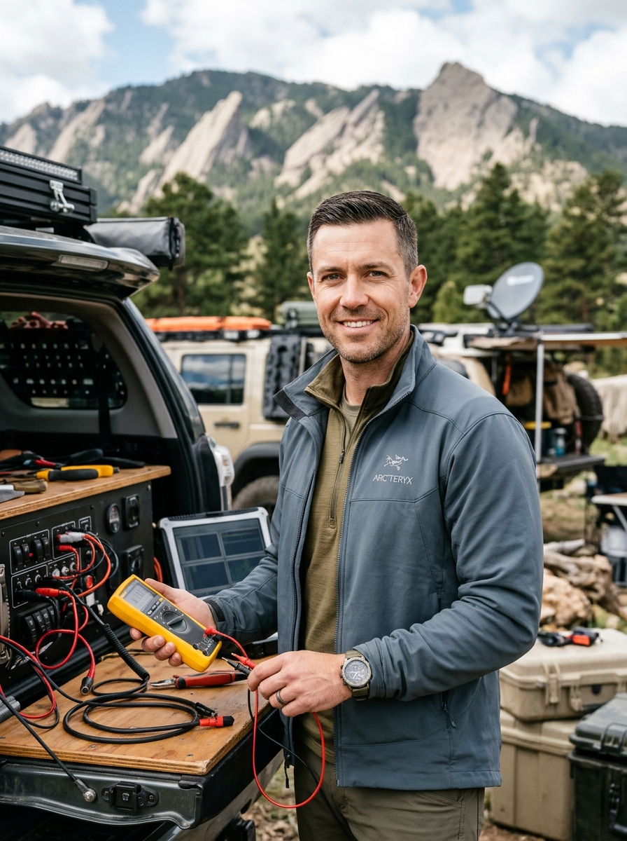
Marcus Vance is a mechanical and electrical systems engineer with 14 years of backcountry telemetry testing across the Rocky Mountains, Mojave Desert, and Cascade Range. Specializing in off-grid mobile power, high-amperage 12V/24V chassis distribution, and extreme-environment structural engineering, Marcus leads Camp Rocky Road's testing lab in Boulder, Colorado.
Related Technical Field Guides
How to Size a LiFePO4 Portable Power Station for Overlanding & 12V Fridges
12V Dual-Zone Camp Fridges: Secop BD35F vs. LG Compressor Duty Cycle Breakdown